Ski-Doo XM / XP
Installation Instructions Hot’n Shreddy Bag
The Hot’n Shreddy installation isn’t a difficult process but does require some disassembly and reassembly of your snowmobile. The instructions below have large photos and detailed process steps to guide your way. The most important thing is to take your time.
Dealer Installation Time: 1 Hour
The Hot’n Shreddy installation is also designed to be completed by a dealer in about an hour, so if you don’t want to take on the project then a dealer can support you with a minimal cost.
Step 1: Remove Plastics
Remove all plastics, this includes:
Display and Glove Box
Left Side Panel
Right Side Panel
Hood (unplug electrical connectors)
Step 2: Disconnect Electrical and remove cowling
Disconnect heated grip and thumb warmer connectors located in front of the steer tube
Disconnect tether wiring connection
Remove gas cap and loosen collar, this should be accomplished without tools and hand pressure.
Remove seat by sliding fingers between front of seat and gas tank until reaching until you feel large plastic tab. Lift up on tab and slide seat backwards.
At the handlebar, lift up the cowling corners to free pins, then remove cowling entirely
Re-attach gas cap


STEP 3: Loosening Rear Triangle OverStructure
Using a 13 mm socket, remove both bolts on both sides of the over structure at the tunnel locations
Using a 10 mm socket and 10mm wrench, remove fasteners on over structure bolts located below the handlebar stem
With over structure completely loose, gently lift up on the rear of the gas tank to free up the over structure connection.
Remove over structure frame completely and set aside
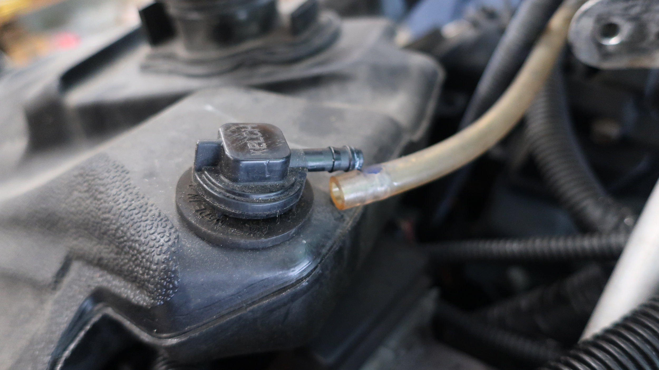
Disconnect fuel tank breather hose from gas tank


STEP 5: Sliding Tank and Disconnecting Electrical Connection
Slowly slide the gas tank backwards a few inches
On the throttle side, behind the pull starter, is an electrical connection which needs to be disconnected. Locate and disconnect it. (see photo below)
Once electrical connector is disconnected, lean fuel tank to throttle side and support with a strap
Mark where Styrofoam pad started with sharpie and then remove pad, remove all tape, clean out any debris, and prep surface with Windex, de greaser, rubbing alcohol, or any other household cleaner. This area will require tape in later steps


STEP 6: Routing electrical wire Under Tank
Locate the ‘Under Tank Wire’ in your kit and take note of the end labeled ‘to rack’
Extend the end labeled ‘To Rack’ 10” past the existing wire connector for tail light. Zip tie wire to the existing wire connector on the brake side of channel.
Secure Under Tank wire with another zip tie to the tail light wire just in 4” in front of the existing wire connector where the plastic cover begins on the channel
Route remaining wire into existing channel and secure Under Tank Wire to existing zip tie location by coolant tubes.
Route excess wire to the right of the airbox following existing factory wiring, securing with a zip tie where necessary.
Leave excess wire towards coolant reservoir on the exhaust side
Add another zip tie in the middle of the wire run in the channel
Cut all zip tie tails and apply duct tape across entire channel
Replace Tank Foam and secure with duct tap


Step 7: Routing Wires to the Hood and Bag
At the rear of the sled, locate the start of the tail light channel on the tunnel and ensure the wire is sticking past with enough revel. Zip tie to clip located on tail light wire channel once reveal has been set.
10” past the connector is the ideal length
8” is minimum access required but hard with gloves to connect
Run the Under Tank Wire towards the hood on the left of the tail light wire and tail light connection, then around the right side of the airbox and follow existing factory wiring run, leaving excess wire in the engine area toward the clutch side of steering tube.
With appropriate wire length set at the tail light channel, begin securing the Under Tank Wire with zip ties to existing factory wiring or wiring mounts; 4 additional zip ties should be plenty. Consult photos for directions.


Step 8: Connect Power and securE excess Wire
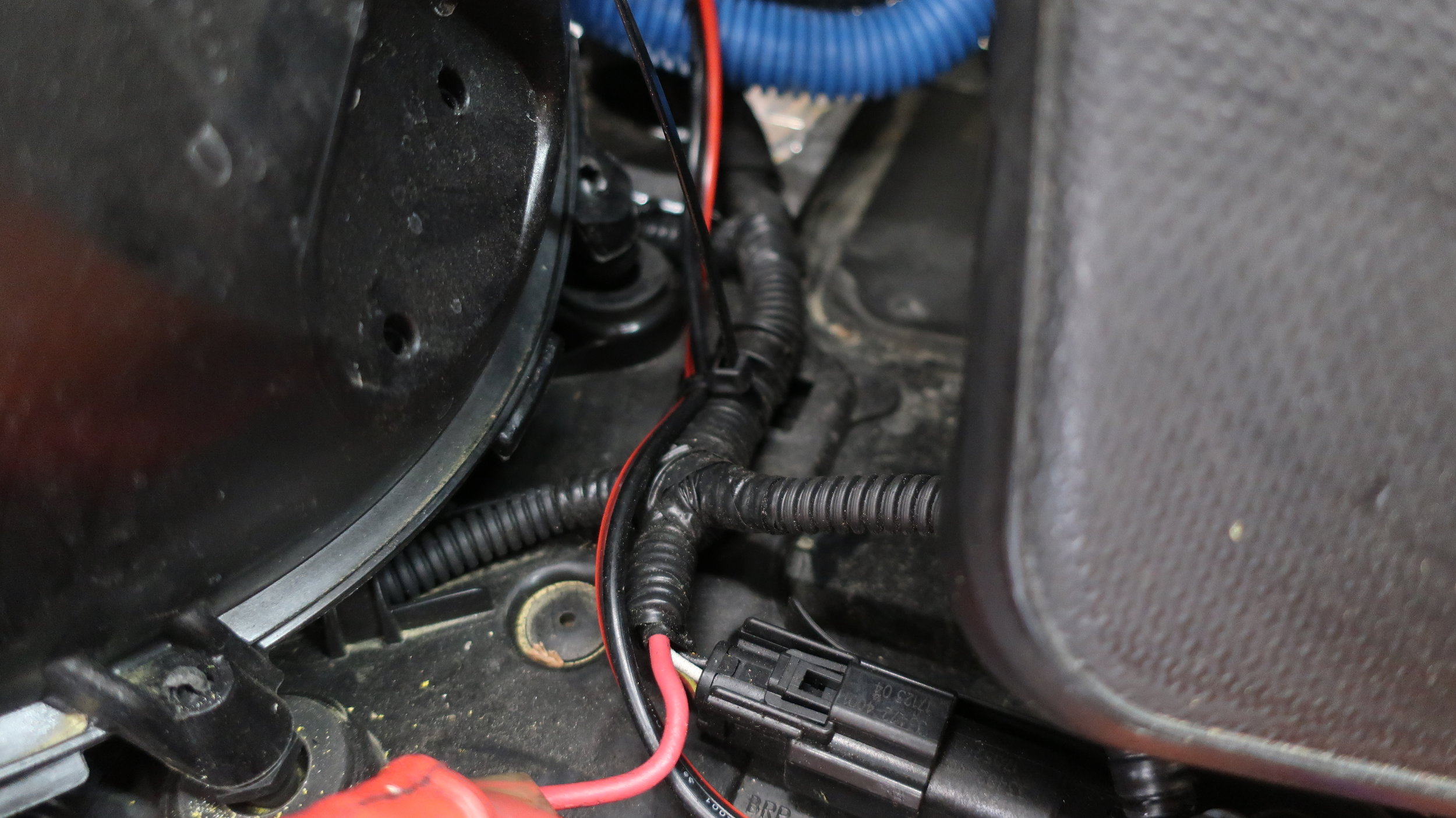
Locate the accessory power connection on the throttle side of the snowmobile, this plug comes directly off of the kill switch tether harness. Connect the Machine Wire Lead supplied in your kit to accessory plug
Connect the Under Tank Wire 2 Prong connector to the Machine Wire two prong connector and bundle the wire
Once connected, secure the excess wire to existing wiring harness behind the coolant bottle with supplied zip ties


Step 9: Assemble Tank, Over Structure Frame, and Console
Connect the electrical wire back to the front of the tank and slide tank forward into place
Loosely assemble all fasteners of over structure at the tunnel and handlebar
Re-attach tank to the snowmobile tunnel with 10 mm bolts and connect breather tube
With over structure back in place tighten all fasteners with 10 mm socket and wrench
Remove gas cap and re-install Console, respective electrical wires, snap in console at handlebar, reinstall gas tank collar, re-install gas cap, and slide on seat


